With the rapid advancement of Additive Manufacturing (AM), the demand for high-quality metal powders has developed in parallel. The necessity for producing superior 3D printed components drives the need for feedstock with optimal technological parameters, specifically high sphericity, uniform particle size distribution, and chemical homogeneity.
Classification of metal atomization methods for powder manufacturing
Materials
Additive Manufacturing
Classification of Powder Manufacturing Methods
Powders are generally produced using various methods, which can be categorized into five main group of methods:
Mechanical
: "Top-down" processes where bulk feedstock is mechanically reduced via milling, crushing, or grinding. These processes primarily yield irregular, sharp-edged, or flattened particles.Physico-mechanical
: The creation of powder by disintegrating liquid metal (atomization). As the droplets solidify, they form primarily spherical particles.Physical
: Processes involving the evaporation and subsequent condensation of metal to form fine, irregular particles.Chemical
: Based on chemical or electrochemical reactions (e.g., sol-gel, electrolysis). Irregular particles are formed from a liquid phase, such as dissolved salts or organic compounds.Physico-chemical
: Primarily reduction processes (e.g., oxide reduction). These yield irregular particles that typically require subsequent milling or spheroidization.
Depending on the chosen manufacturing process, the powders will exhibit a specific set of advantages and disadvantages. However, given the rigorous requirements of 3D printing – where sphericity and purity are paramount – atomization, have dominated the industry for AM feedstock production.

Gas atomization (<75 µm)

Mechanical milling & spheroidization (<63 µm)

Water atomization (<45 µm)

Ultrasonic atomization (unsieved, atomized at 36 KHz)
Atomization Process Categories
Most classical atomizers share a common architecture: a melting section, an atomizing chamber and downstream transport, drying, and sieving systems to collect, de-gas, dry (if needed), and classify the powder by size. Atomization processes are divided into two fundamental categories based on the disintegration mechanisms
1. Single Fluid Atomization
This methods utilizes mechanical energy and physical phenomena within the liquid itself, without an external atomizing medium. On an industrial scale, techniques such as the following are widely employed:
-
Centrifugal Atomization (CA):
Molten metal is poured onto a rotating disk or cup, where centrifugal force breaks the liquid into streams and droplets. It is primarily used for metals with lower melting points (Pb, Sn, Zn, Al) to minimize erosion of the atomizing disks. -
Plasma Rotating Electrode Process (PREP):
Uses a rapidly rotating electrode melted by a plasma arc. This allows for the production of highly spherical particles with high purity. The process is successfully used for reactive and refractory alloys, but it requires precise machined rod electrodes. -
Ultrasonic Atomization (UA)
is a method that utilizes high-frequency (ultrasound) vibrations to generate a mist from molten metal, which solidifies to form highly spherical powder, providing a high degree of flexibility regarding the applied feedstock and the melting method.
2. Two Fluid Atomization
Disintegration occurs via the interaction between molten metal and a high-pressure external stream.
-
Gas Atomization (GA)
: Uses compressed gas, most commonly inert Ar or N2, to atomize the metal stream. This is most commonly used process in large scale industrial powder production for metal AM. -
Water Atomization (WA)
: Uses water or oil under very high pressure as the dispersing medium. It allow to produce very fine powders, but with low sphericity. It is commonly uses for production of feedstock for powder metallurgy and metal injection moulding (MIM).
In summary, Single Fluid methods primarily employ centrifugal force, mechanical vibrations or ultrasound, while Two Fluid methods rely on the kinetic energy of compressed gas, liquid, or gas-liquid mixtures. Industrial processes occasionally employ hybrid configurations, combining two different atomization methods like centrifugal atomization with gas or water atomization.
Melting Technologies and Process Control
A critical stage preceding atomization is melting. The method selected depends primarily on the alloy’s melting point and chemical reactivity. In AM powder production, high-performance processes are mostly used. Common advanced melting methods in GA include:
VIGA (Vacuum Induction Melting Inert Gas Atomization):
The most popular melting process for gas atomization. Feedstock is melted in an induction furnace under vacuum or low pressure. This is crucial for high purity, effectively removing dissolved harmful gases like oxygen or hydrogen.VIGA-CC (Vacuum Induction Melting Gas Atomization with a Cold Crucible):
A specialized modification of VIGA using a water-cooled copper crucible instead of ceramic. This eliminates the risk of contaminating the alloy with ceramic crucible material, which is critical for reactive alloys.EIGA (Electrode Induction Melting Inert Gas Atomization):
Dedicated to high-reactivity materials like Ti or Zi. A slowly rotating electrode is melted directly inside an induction coil. In this solution, the liquid metal never contacts a crucible, ensuring high powder purity.PIGA (Plasma Melting Induction Guiding Gas Atomization):
Material is melted by a plasma arc, and the flowing liquid is superheated via induction. The entire process occurs in a cooled copper crucible, similar to VIGA-CC.ECR-CIG (Electroslag Remelting – Cold Wall Induction Guided):
A process involving electroslag refining, where liquid passes through a slag layer before being heated in a cold crucible via induction. This is used for applications requiring extremely clean, low oxygen, alloys with strict chemical composition control.
A major technological challenge during melting process is maintaining the precise chemical composition and low oxide level. Phenomena such as selective evaporation of elements with high vapor pressure or reactions between molten metal and the crucible can lead to compositional changes and oxide inclusions. Therefore, for highly reactive alloys with high oxygen affinity (e.g., Ti, Zr alloys), ceramic crucible-free methods like VIGA-CC, EIGA, or PIGA are essential.
Detailed Mechanism of Droplet Formation
Once the liquid metal achieves the required parameters, it is directed to the atomization chamber. The key stage is the formation of a thin stream and its subsequent breakup into droplets.
- In gas, water and centrifugal atomization furnace is located in upper part of atomizer. Liquid metal is poured through nozzle to atomization chamber where the liquid stream is distributed by gas/water under high pressure or centrifugal force on rotating disk. Liquid droplets solidified in big atomizing chamber and was transported to collection chamber.
- In the PREP process, the feedstock takes the form of a rapidly rotating electrode rod, the face of which is melted by a plasma arc. The resulting thin liquid film is sheared off the edge of the bar by the high rotational speed and centrifugal force. This mechanism forms spherical droplets that solidify in flight within an inert gas atmosphere. By eliminating contact with crucibles or nozzles, this method guarantees the high purity essential for aerospace and medical applications.
- Ultrasonic Atomization offers an interesting development in atomization technologies because it is one of the most flexible approaches with respect to melting configurations. Depending on the system design, it can enable crucible-free melting using an electric arc or plasma arc, where a wire or rod is melted directly onto a vibrating platform—and, in these arc/plasma configurations, melting and atomization can be integrated into a single workspace. It can also be configured for induction melting of a rod in an induction coil, in a manner similar to the EIGA process, as well as for conventional induction melting in a crucible. In these systems, ultrasonic vibrations transfer to the molten metal, forming capillary waves on the melt surface. Droplets detach from the wave crests, creating a metallic mist with a very narrow and precise particle size distribution.
Powder Requirements for 3D Printing
Metal powders are the standard feedstock for AM methods such as Powder Bed Fusion (PBF), Binder Jetting, and Directed Energy Deposition (DED). In PBF processes, powder layers are melted using a focused laser source (PBF-LB/M) or an electron beam (PBF-EB/M). Binder Jetting involves bonding the powder with a precisely dosed binding agent. Similarly, DED processes melt powder using concentrated laser (DED-LB) or electron beam (DED-EB) energy, requiring precise delivery of the powder through a nozzle system directly into the melt pool.
For 3D printing, it is particularly important to use powders with a strictly defined Particle Size Distribution (PSD), high flowability, maximum apparent density, and high sphericity. Additionally, powders should be chemically homogeneous, dry, and have low oxygen content. The geometry of the particle determines its behavior in the 3D printer: a spherical shape ensures free flow and allows for high packing density in the layer, which is fundamental for obtaining a uniform material. Typical PSD ranges for AM technologies are:
A major limitation in powder production is the typically very broad PSD. In GA, CA, and PREP, it is difficult to achieve a high yield of powders with diameters below a few tens of micrometers; therefore, only a narrow fraction is suitable for AM—especially for LPBF. The majority of the powder fractions are bigger and are repurposed for other powder metallurgy processes. In contrast, in UA the powder PSD is strongly dependent on the ultrasound frequency and can be tuned within the operating range of the vibration generator.
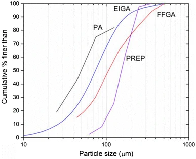
Atomization methods PSD
Ultrasonic atomization PSD
Metal Powder Defects
final 3D printed components. Several morphological defects can occur during atomization:
Satellites
: Small particles permanently attached to the surface of larger grains. The mechanism depends on the temperature at collision. If the collision between particles occurs in the temperature range between liquidus and solidus, the smaller particle partially fuses into the larger one. At temperatures below the solidus line, the fine fraction "welds" to the already solidified surface (Figure 2a,d).Splat Caps:
Specific defects appearing as "caps" on particle surfaces. They form when a solidified particle collides with a liquid metal droplet (or vice versa). The collision causes the liquid phase to flatten on the solid surface and solidify instantly (Figure 2a).Cracks:
Fractured particles typically result from high-velocity collisions between particles or with the atomization chamber walls. The kinetic energy of the impact leads to cracking, which is particularly problematic for hard and brittle alloys (Figure 2c).Gas Porosity:
The entrapment of gas bubbles inside the powder particle is characteristic of gas atomization, where high-pressure gas is trapped during droplet formation.Elongated and irregular particles:
Deviations from sphericity, often occurring in centrifugal and water atomization. They result from disturbances in droplet formation or rapid solidification occurring before surface tension can shape the particle into a sphere. The proportion of non-spherical particles is strongly dependent on cooling rates and particle interaction. It is highest in water atomization (due to rapid heat extraction) and lowest in PREP and ultrasonic methods (Figure 2e).Surface Oxidation and contaminations:
Surface oxidation does not result solely from improper powder storage, but primarily from the manufacturing process and gas atmosphere. In gas atomization, this risk is minimized by using inert gases. The situation is different in water atomization, where the high process temperature can decompose water molecules into hydrogen and oxygen, leading to rapid surface oxidation. Additionally, powders produced this way require drying, further promoting oxide formation.
In addition to morphology defects, powders often exhibit problems related to chemical homogeneity and purity. These primarily include elemental segregation, resulting from rapid solidification rates or impurities during melting (Figure 2f).

Splat cap in CoCrMo

satellites in Inconel 625

Cracked particle in Inconel 625

Satellites and agglomerates in Al10SiMg

elongated particles in 316L steel,

Fe segregation on Al7SiMg particle
Comparison of Metal Atomization Methods
Gas Atomization

Uses compressed gas, most commonly inert Ar or N2, to atomize the metal stream. This is most commonly used process in large scale industrial powder production for metal AM.
Advantages of Gas Atomization
- Highly scalable
- Good sphericity
- Broadest industry adoption
- Fine fraction suitable for AM
Limitations of Gas Atomization
- Very high gas cost
- Satellites
- Possible crucible/nozzle contamination
- Broad PSD
- Low amount of fine fraction
Gas Atomization technical characteristics
- Typical feedstock
- Casted alloy, rod
- Melting process
- Induction melting, plasma melting or electroslag remelting.
- Atomization mechanism
- Gas
- Materials
- Wide range of alloys, depends on the melting process, limitation for high melting point materials
- Typical atmosphere
- Inert gas (Ar/N2)
- Particle size (PSD)
- Typically medium-to-coarse, tunable via gas pressure and nozzle type, Material depend
- Typical morphology
- Generally high sphericity with, satellites, splat caps, gas porosity
- Contaminations
- Low oxygen, some contaminations from crucible/nozzle contact
- Equipment size
- Large to Very large Tall atomization tower with gas system
- Productivity
- High (industrial scale)
- Flexibility
- Low – dedicated for one material, time and cost consumable material change
Water Atomization

Uses high-pressure water, or in some systems oil, to atomize the molten metal stream. It is a high-output and cost-efficient process commonly used for powder metallurgy and Metal Injection Molding applications.
Advantages of Water Atomization
- Lowest cost per kilogram
- Very high output
- Cost-efficient production
- Well suited for powder metallurgy and MIM
Limitations of Water Atomization
- Higher oxygen content due to water interaction
- Irregular particle morphology
- Low powder flowability
- Generally not recommended for AM powders
Water Atomization technical characteristics
- Typical feedstock
- Casted alloy
- Melting process
- Induction melting
- Atomization mechanism
- Water or oil
- Materials
- Wide range of alloys, with limitations for high melting point materials
- Typical atmosphere
- Inert gas (Ar/N₂), with water used as the atomizing medium
- Particle size (PSD)
- Wide particle size distribution, with a significant amount of fine particles. Material dependent
- Typical morphology
- Irregular particle morphology
- Contaminations
- High oxygen content caused by interaction with water
- Equipment size
- Medium to very large - tall atomization tower with water pumps, additional filtration and drying systems
- Productivity
- Very high and cost-efficient
- Flexibility
- Low - typically dedicated to one material, with time-consuming and costly material changeovers
Centrifugal Atomization

Uses a rapidly rotating, water-cooled disc or cup to break the molten metal stream into droplets through centrifugal force. The process provides good control over particle size and is mainly suitable for low-melting-point alloys and powder metallurgy applications.
Advantages of Centrifugal Atomization
- Relatively narrow particle size distribution
- Good particle sphericity
- Good PSD control through rotation speed
- No high-pressure gas required
- Suitable for powder metallurgy
Limitations of Centrifugal Atomization
- Limited mainly to low-melting-point alloys
- Lower throughput compared with GA and WA
- Possible contamination from the atomization disc
- Elongated particles may occur
Centrifugal Atomization technical characteristics
- Typical feedstock
- Casted alloy
- Melting process
- Induction melting
- Atomization mechanism
- Water-cooled rotating disc or cup
- Materials
- Low-melting-point alloys
- Typical atmosphere
- Inert gas (Ar/N₂)
- Particle size (PSD)
- Relatively narrow, with good control through rotation speed and a low amount of fine particles. Material dependent
- Typical morphology
- High sphericity, with possible elongated particles and a low amount of satellites
- Contaminations
- Low oxygen content, with possible contamination from the atomization disc
- Equipment size
- Medium to very large - tall atomization tower with a wide chamber
- Productivity
- Medium - lower than GA and WA
- Flexibility
- Low - typically dedicated to one material, with time-consuming and costly material changeovers
Plasma Rotating Elecrode Process (PREP)

Uses a plasma arc to melt the end of a high-speed rotating metal rod. Centrifugal force ejects molten droplets from the rod, producing highly spherical powder suitable for additive manufacturing, including reactive and high-temperature alloys.
Advantages of Plasma Rotating Elecrode Process (PREP)
- High particle sphericity
- Low amount of satellites
- Suitable for reactive and high-temperature alloys
- Crucible-free process
- Suitable for AM applications
Limitations of Plasma Rotating Elecrode Process (PREP)
- Requires machined, high-quality rods
- High cost of feedstock
- Limited feedstock availability
- Low-to-medium productivity
Plasma Rotating Elecrode Process (PREP) technical characteristics
- Typical feedstock
- Machined rod
- Melting process
- Plasma arc
- Atomization mechanism
- Centrifugal force generated by the high-speed rotation of the rod
- Materials
- Wide range of materials, with limitations for low-melting-temperature materials
- Typical atmosphere
- Inert gas (Ar/N₂)
- Particle size (PSD)
- Narrow particle size distribution, controlled by rotation speed. Material dependent, with a low amount of fine particles
- Typical morphology
- High sphericity, with possible elongated particles and a low amount of satellites
- Contaminations
- Low oxygen content
- Equipment size
- Medium - rotating column with a plasma system and rotating electrode system
- Productivity
- Low-to-medium
- Flexibility
- Medium - suitable for small batches and difficult-to-atomize alloys
Ultrasonic Atomization

Uses high-frequency ultrasonic vibrations to break molten metal into fine droplets. The process enables precise particle size control, high sphericity and flexible integration with different melting methods, making it suitable for laboratory-scale production, small batches and material recycling.
Advantages of Ultrasonic Atomization
- High particle sphericity
- Narrow and precise particle size distribution
- Low amount of satellites
- Flexible integration with different melting processes
- Suitable for a wide range of materials
- Crucible-free option and material recycling
Limitations of Ultrasonic Atomization
- Limited industrial scalability
- Low-to-medium throughput
- High sonotrode costs
- Possible contamination from the atomization platform
Ultrasonic Atomization technical characteristics
- Typical feedstock
- Casted alloy, wire or rod
- Melting process
- Induction melting, gas arc or plasma arc
- Atomization mechanism
- Ultrasonic vibrations
- Materials
- Wide range of alloys, with flexibility depending on the melting process
- Typical atmosphere
- Inert gas (Ar)
- Particle size (PSD)
- Narrow and precise particle size distribution, controlled by ultrasonic frequency
- Typical morphology
- High sphericity with a low amount of satellites
- Contaminations
- Low oxygen content, with possible contamination from the atomization platform
- Equipment size
- Small to medium - compact, modular system suitable for laboratory-scale production
- Productivity
- Low-to-medium
- Flexibility
- High - suitable for small batches, material recycling and a wide range of materials
Bibliography
- Zhou, Z., Sun, W., Lu, W., Zhang, S. and Wang, J. (2025), Advancements in Understanding the Characteristics of Gas Atomized Powders: A Review. Adv. Eng. Mater., 27: 2500270. https://doi.org/10.1002/adem.202500270
- Henein, H., Uhlenwinkel, V., & Fritsching, U. (Eds.). (2017). Metal sprays and spray deposition (1st ed.). Springer Cham. https://doi.org/10.1007/978-3-319-52689-8
- Anderson, I. E., White, E. M. H., & Dehoff, R. (2018). Feedstock powder processing research needs for additive manufacturing development. Current Opinion in Solid State and Materials Science, 22(1), 8–15. https://doi.org/10.1016/j.cossms.2018.01.002


